
Solution for planetary gearbox shaft breakage
Release Time:
2024-10-15
Before installation, wipe off the rust proof oil on the motor input shaft, positioning boss, and reducer connection parts with gasoline or zinc sodium water. Its purpose is to ensure the tightness of the connection and the flexibility of operation, while preventing unnecessary wear and tear. Before connecting the motor to the reducer, please align the keyway of the motor shaft perpendicular to the tightening bolt. To ensure even force distribution, please first tighten the installation bolts at any diagonal position, but do not tighten them, then tighten the installation bolts at the other two diagonal positions, and finally tighten the four installation bolts one by one. Finally, tighten the tension bolt. All tightening bolts need to be fixed and checked with a torque wrench according to the indicated fixed torque data. The relevant data of the right angle reducer is not exactly the same as that of the same model of linear reducer, please pay attention to it. The correct installation between the gearbox and mechanical equipment is similar to the correct installation between the gearbox and the drive motor. The key is to ensure that the concentricity between the output shaft of the reducer and the driven shaft is consistent.
In order to better assist users in using planetary reducers, this article analyzes the causes of shaft breakage in reducers and drive motors, and provides detailed instructions on how to correctly install planetary reducers to prevent shaft breakage.
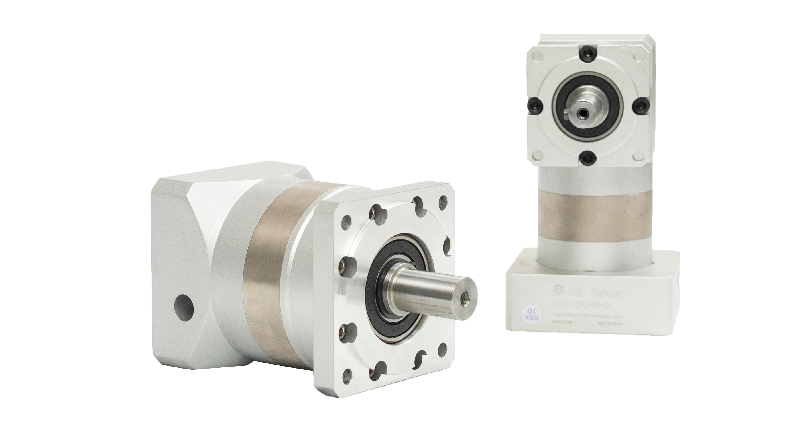
Some users break the output shaft of the drive reducer after the device has been running for several months. Why did the gearbox break the output shaft of the drive motor? We examined the cross-section of the output shaft of the drive motor and found that it was almost identical to the cross-section of the output shaft of the gearbox. The outer ring of the cross-section is brighter, while the color of the cross-section becomes darker towards the axis, and finally it breaks at the axis! This fully illustrates that the main reason for the breakage of the output shaft of the drive motor is that the motor and the reducer are not concentric during assembly!
When the concentricity between the motor and the reducer is ensured very well during assembly, the output shaft of the motor only bears the rotational force and runs smoothly. However, when they are not concentric, the output shaft has to bear radial forces from the input end of the reducer. The long-term effect of this radial force will force the motor output shaft to bend, and the direction of bending will constantly change with the rotation of the output shaft. The direction of lateral force changes 360 degrees for every rotation of the output shaft. If the concentricity error is large, the radial force will cause the temperature of the motor output shaft to rise, and its metal structure will be continuously damaged. Eventually, the radial force will exceed the radial force that the motor output shaft can withstand, leading to the breakage of the drive motor output shaft. The larger the concentricity error, the shorter the time it takes for the output shaft of the drive motor to break. At the same time as the output shaft of the driving motor breaks, the input end of the reducer will also bear radial forces from the motor. If this radial force exceeds the maximum radial load that both can bear, the result will also cause deformation or even fracture of the input end of the reducer. Therefore, ensuring concentricity during assembly is crucial! Intuitively speaking, if the motor shaft and the input end of the gearbox are concentric, the fit between the motor and gearbox will be very tight, and their contact surfaces will be tightly connected. However, if they are not concentric during assembly, there will be gaps between their contact surfaces. The left side of Figure 3 shows that the assembly between the motor and the reducer is good, while the right side shows that the assembly is not good and the motor shaft and reducer shaft are broken. Considering that this situation occurs frequently, we will further introduce it here.
The first step is to confirm whether the motor and reducer are intact before installation, and strictly check whether the dimensions of each part connected to the motor and reducer match. Here are the dimensions and fitting tolerances of the motor's positioning boss, input shaft, and reducer groove.
The second step is to unscrew the screws on the outer dust-proof hole of the reducer flange, adjust the PCS system clamping ring to align its side hole with the dust-proof hole, and insert it into the hexagonal socket for tightening. Afterwards, remove the motor shaft key.
The third step is to naturally connect the motor to the reducer. When connecting, it is necessary to ensure that the concentricity between the output shaft of the reducer and the input shaft of the motor is consistent, and the outer flanges of the two are parallel. Inconsistent alignment can cause the motor shaft to break or the gear of the gearbox to wear. In addition, during installation, it is strictly prohibited to strike with hammers or other tools to prevent excessive axial or radial forces from damaging bearings or gears. Be sure to tighten the installation bolts before tightening the tension bolts.
Before installation, wipe off the rust proof oil on the motor input shaft, positioning boss, and reducer connection parts with gasoline or zinc sodium water. Its purpose is to ensure the tightness of the connection and the flexibility of operation, while preventing unnecessary wear and tear. Before connecting the motor to the reducer, please align the keyway of the motor shaft perpendicular to the tightening bolt. To ensure even force distribution, please first tighten the installation bolts at any diagonal position, but do not tighten them, then tighten the installation bolts at the other two diagonal positions, and finally tighten the four installation bolts one by one. Finally, tighten the tension bolt. All tightening bolts need to be fixed and checked with a torque wrench according to the indicated fixed torque data. The relevant data of the right angle reducer is not exactly the same as that of the same model of linear reducer, please pay attention to it. The correct installation between the gearbox and mechanical equipment is similar to the correct installation between the gearbox and the drive motor. The key is to ensure that the concentricity between the output shaft of the reducer and the driven shaft is consistent.
Related News