
Structure and working principle of gearbox
Release Time:
2024-10-10
The small gear is integrated with the high-speed shaft, using a gear shaft structure. This structure is used in situations where the diameter of the gear and the diameter of the shaft are not significantly different. The large gear is assembled on the low-speed shaft, and the parts on the shaft are fixed axially using shaft shoulders, shaft sleeves, and bearing covers. Due to the axial force during gear meshing, both shafts are supported by a pair of tapered roller bearings to withstand the combined effects of radial and axial loads. The bearing is lubricated with lubricating oil. To prevent the hot oil from gear meshing from directly entering the bearing, an oil stop ring is installed on the inner wall of the box located in the bearing seat hole between the bearing and the small gear. To prevent lubricant leakage from the box at the joint between the shaft extension section and the bearing cover, as well as external dust and foreign objects entering the box, a sealing element is installed in the bearing cover. The contact type lip seal ring used in the picture is suitable for dusty environments.
Gearboxes are generally used for low-speed and high torque transmission equipment. They reduce the speed of electric motors, diesel engines, or other high-speed power by using gears with fewer teeth on the input shaft of the gearbox to mesh with the large gear on the output shaft. Ordinary gearboxes also have several pairs of gears with the same principle to achieve the desired reduction effect. The ratio of the number of teeth between the large and small gears is the transmission ratio.
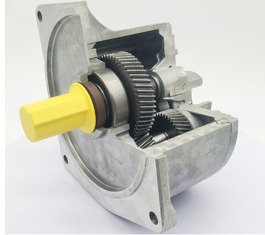
The gearbox mainly reduces the speed and increases the torque. It has a wide variety of types, different models, and different types have different purposes. There are various types of gearboxes, which can be divided into gear gearboxes, worm gearboxes, and planetary gearboxes according to their transmission types; According to the different transmission stages, it can be divided into single-stage and multi-stage gearboxes; According to the shape of the gears, they can be divided into cylindrical gear reducers, bevel gear reducers, and cone cylindrical gear reducers; According to the arrangement of transmission, it can be divided into expansion type, diversion type, and coaxial type gearboxes.
The first stage cylindrical gear reducer achieves deceleration motion through the rotation of a pair of meshing gears installed inside the gearbox. The power is transmitted from the electric motor to the gear shaft through the pulley, and then transmitted to the shaft through two meshing gears (the small gear drives the large gear) to achieve the purpose of deceleration.
Gearbox structure
The small gear is integrated with the high-speed shaft, using a gear shaft structure. This structure is used in situations where the diameter of the gear and the diameter of the shaft are not significantly different. The large gear is assembled on the low-speed shaft, and the parts on the shaft are fixed axially using shaft shoulders, shaft sleeves, and bearing covers. Due to the axial force during gear meshing, both shafts are supported by a pair of tapered roller bearings to withstand the combined effects of radial and axial loads. The bearing is lubricated with lubricating oil. To prevent the hot oil from gear meshing from directly entering the bearing, an oil stop ring is installed on the inner wall of the box located in the bearing seat hole between the bearing and the small gear. To prevent lubricant leakage from the box at the joint between the shaft extension section and the bearing cover, as well as external dust and foreign objects entering the box, a sealing element is installed in the bearing cover. The contact type lip seal ring used in the picture is suitable for dusty environments.
Related News