
Working principle and application analysis of deceleration motor
Release Time:
2025-07-16
The core of a gearbox lies in the transmission ratio of the gear set. The two mainstream structures, planetary gears and worm gears, each have their own characteristics: planetary gears have high efficiency but complex structures, while worm gears can self lock but have low efficiency.
Working principle and application analysis of deceleration motor
The key to the problem of deceleration motor is to clarify how the two parts of "deceleration" and "motor" work together. We have to start with the motor itself - whether it is a DC motor or an AC motor, they generally output high speed and low torque, which is often not sufficient in practical applications. For example, when an electric push rod needs to move vigorously and slowly, a gearbox is needed to take effect.
The core of a gearbox lies in the transmission ratio of the gear set. The two mainstream structures, planetary gears and worm gears, each have their own characteristics: planetary gears have high efficiency but complex structures, while worm gears can self lock but have low efficiency.
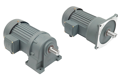
A deceleration motor is a power transmission device that converts the high-speed rotational motion of an electric motor into low-speed, high torque output. It is widely used in fields such as mechanical manufacturing, automated production lines, and logistics equipment. Its working principle can be analyzed in detail from two aspects: core composition and motion transmission process:
1、 Core components
The deceleration motor mainly consists of two parts:
Drive part (electric motor)
Provide original power, usually DC motor, AC motor or servo motor, outputting high-speed rotational motion (speed can reach thousands of revolutions per minute), but with small torque.
Deceleration section (reducer)
Composed of mechanical structures such as gears, worm gears, planetary gears, etc., its core function is to reduce speed and increase torque. Its design is based on the principle of "gear ratio": by meshing gears with different numbers of teeth, the speed and torque of power transmission are changed.
2、 Working principle: Conversion from high speed to low speed
Power input
After the electric motor is powered on, it rotates and its output shaft (high-speed shaft) is connected to the input gear (driving wheel) of the reducer, transmitting high-speed motion to the reducer.
Deceleration transmission process
The internal reduction of the reducer is achieved through multi-stage gear meshing. Taking a common gear reducer as an example:
When the driving wheel (with fewer teeth) meshes with the driven wheel (with more teeth), the driving wheel rotates multiple times while the driven wheel rotates only once.
For example, the number of driving teeth is 10, the number of driven wheels is 50, and the transmission ratio is 1:5 (i.e. the driving wheel rotates 5 turns and the driven wheel rotates 1 turn).
If it is a multi-stage gear set, the total transmission ratio is the product of the transmission ratios of each stage (such as a two-stage transmission ratio of 1:5 × 1:5=1:25), and the final output speed is significantly reduced.
Torque variation law
According to the principle of energy conservation (ignoring losses), power=rotational speed x torque. When the speed decreases, the torque increases proportionally (for example, when the transmission ratio is 1:5, the torque increases by about 5 times), thereby meeting the mechanical device's demand for high torque (such as lifting and conveying).
Output power
The output shaft (low-speed shaft) of the reducer transmits low-speed, high torque motion to the working machinery (such as conveyor belts, agitator blades) to complete the driving task.
Related News