
The structural principle and installation method of planetary gearbox
Release Time:
2024-09-21
The correct installation between the gearbox and mechanical equipment is similar to the correct installation between the gearbox and the drive motor. The key is to ensure that the concentricity between the output shaft of the reducer and the driven shaft is consistent.
It consists of the main body, output shaft, output shaft oil seal, output bearing, sun nut, planetary carrier, internal gear ring, planetary gear, stage gear, needle roller shaft, sun gear, C-type buckle ring, input bearing, input shaft oil seal, input flange, O-ring, vent plug, key, washer, hexagon socket screw, etc.
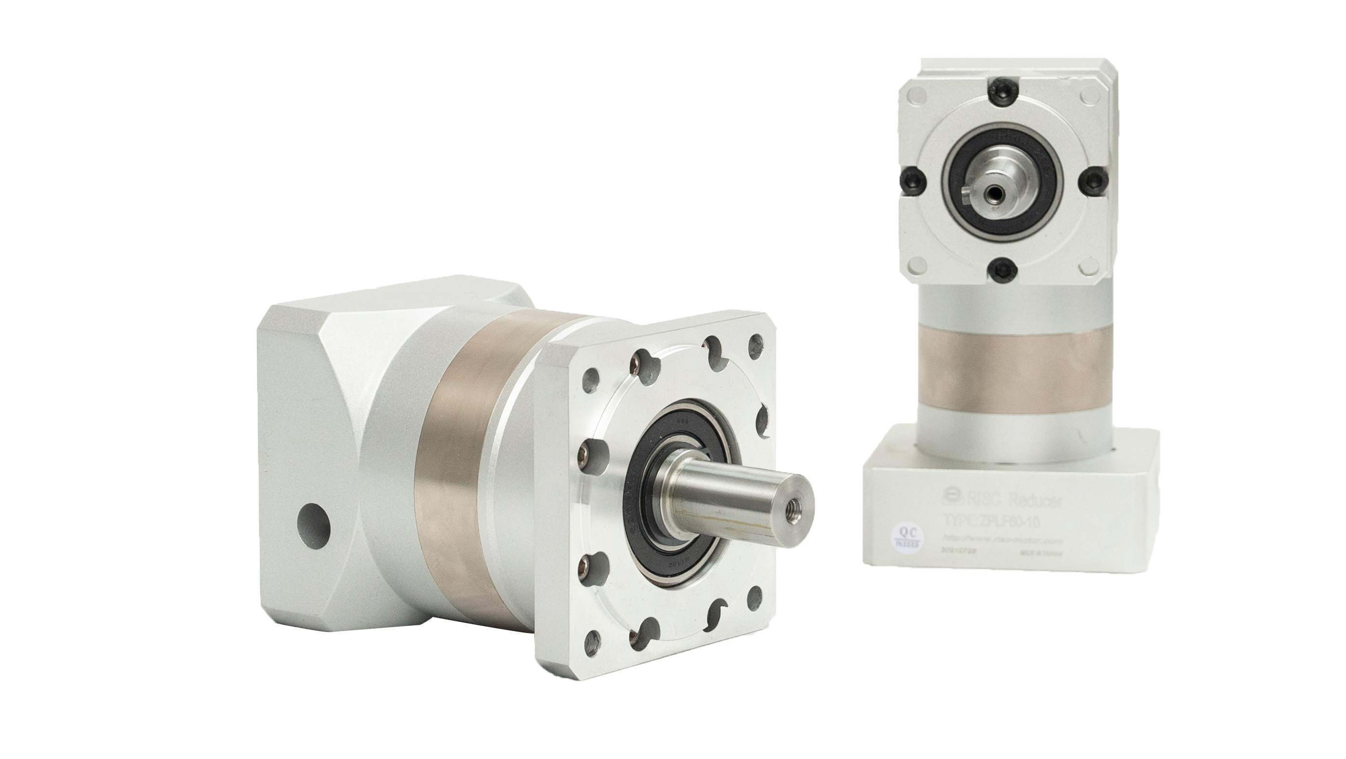
1. Transmission principle
The transmission structure of a planetary gearbox is currently the most efficient combination of gear reducers, and its basic transmission structure consists of four parts:
① Sun gear.
② Planetary gears (combined with planetary carriers).
③ Internal gear ring.
④ Stage gears.
The drive source starts the sun gear in a direct connection, and the sun gear is combined with the planetary gears on the planetary gear carrier to drive the operation. The entire planetary gear system automatically rotates along the outer gear ring, and the planetary carrier is connected to the output shaft to achieve acceleration. A higher reduction ratio requires multiple sets of stage gears and planetary gears to be multiplied and accumulated.
2. Deceleration characteristics
(1) High torque and impact resistance: The mechanism of planetary gears is similar to the transmission mode of traditional parallel gears. Traditional gears rely only on a very small number of contact surfaces between two gears for squeezing and driving, and all loads are concentrated on the few gear surfaces in contact, which can easily cause friction and fracture between gears. The planetary gear reducer has six larger areas and 360 degree uniform loads on the gear contact surface. Multiple gear surfaces jointly and uniformly bear instantaneous impact loads, making it more capable of withstanding higher torque forces. The body and various bearing parts will not be damaged or broken due to high loads.
(2) Small size and light weight: Traditional gear reducers are designed with multiple sets of large and small gears inclined towards staggered transmission reduction. Due to the fact that the reduction ratio needs to be generated by a multiple of the number of two gears, there must be a certain distance between the large and small gears for meshing. Therefore, the space for accommodating the gearbox is extremely large. Especially when combining high-speed ratios, it is necessary to connect and combine two or more reduction gearboxes, which relatively weakens the structural strength and prolongs the length of the gearbox, resulting in extremely large volume and weight. The structure of the planetary gearbox can be repeatedly connected according to the required number of segments, and multiple segments can be combined separately. It has a small volume, light weight, and lightweight appearance, making the design more valuable.
(3) High efficiency and low backlash: Due to the fact that each set of gears in the gear reducer only has a single tooth surface meshing contact during transmission, greater tooth surface stress is required when the transmission torque is equal. Therefore, larger module and thickness must be used in gear design. The larger the gear module, the greater the deviation tolerance between gears, resulting in relatively high gear backlash. The cumulative backlash between each reduction ratio increases accordingly. The unique multi-point uniform sealing in the planetary gear combination, coupled with the circular arc enveloping structure of the outer gear ring, ensures a tight fit between the outer gear ring and the planetary gears, resulting in a high degree of sealing between the gears. In addition to improving the efficiency of the gearbox, the design itself can achieve high-precision positioning.
3. Installation method
In the reducer family, planetary reducers are widely used in servo, stepper, DC and other transmission systems due to their small size, high transmission efficiency, wide reduction range, and high precision. Its function is mainly used to reduce speed, increase torque, and reduce the load/motor moment of inertia ratio while ensuring precision transmission.
Proper installation, use, and maintenance of reducers are important steps in ensuring the normal operation of mechanical equipment. Therefore, when installing the planetary gearbox, please strictly follow the following installation and use related matters, and assemble and use it carefully.
Before installation, confirm that the motor and reducer are intact and undamaged, and strictly check whether the dimensions of each part connected to the motor and reducer match. Here are the dimensions and fitting tolerances of the motor's positioning protrusion, input shaft, and reducer groove.
Unscrew the screws on the outer dust-proof hole of the reducer flange, adjust the PCS system clamping ring to align its side hole with the dust-proof hole, and insert it into the hexagonal socket for tightening. Afterwards, remove the motor shaft key.
Connect the motor and reducer naturally. When connecting, it is necessary to ensure that the concentricity between the output shaft of the reducer and the input shaft of the motor is consistent, and the outer flanges of the two are parallel. Inconsistent alignment can cause the motor shaft to break or the gear of the gearbox to wear.
Attention: It is strictly prohibited to use hammers or other tools to strike, in order to prevent excessive axial or radial force from damaging bearings or gears. Be sure to tighten the installation bolts before tightening the tension bolts.
Before installation, wipe off the rust proof oil on the motor input shaft, positioning boss, and reducer connection parts with gasoline or zinc sodium water.
Before connecting the motor to the reducer, the keyway of the motor shaft should be perpendicular to the tightening bolt. To ensure even force distribution, first tighten the installation bolts at any diagonal position, but do not tighten them, then tighten the installation bolts at the other two diagonal positions, and finally tighten the four installation bolts one by one.
Finally, tighten the tension bolt. All tightening bolts need to be fixed and checked with a torque wrench according to the indicated fixed torque data.
The correct installation between the gearbox and mechanical equipment is similar to the correct installation between the gearbox and the drive motor. The key is to ensure that the concentricity between the output shaft of the reducer and the driven shaft is consistent.
Related News