
Cycloidal pin wheel reducer
Release Time:
2025-04-15
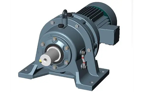
Cycloid pinwheel reducer is a novel transmission device that applies the principle of planetary transmission and adopts cycloidal pinwheel meshing. The transmission device of the cycloidal pinwheel reducer can be divided into three parts: input part, reduction part, and output part.
Cycloidal pin wheel reducer
Cycloid pinwheel reducer is a novel transmission device that applies the principle of planetary transmission and adopts cycloidal pinwheel meshing. The transmission device of the cycloidal pinwheel reducer can be divided into three parts: input part, reduction part, and output part. A double eccentric sleeve with a 180 ° misalignment is installed on the input shaft, and two roller bearings called rotating arms are installed on the eccentric sleeve to form an H mechanism. The center holes of the two cycloidal gears are the raceways of the rotating arm bearings on the eccentric sleeve, and the cycloidal gears mesh with a set of annular arranged needle teeth on the needle gear to form an internal meshing reduction mechanism with a tooth difference of one tooth (in order to reduce friction, needle teeth are equipped with needle tooth sleeves in reducers with low speed ratios).
1、 Institution Introduction
When the input shaft rotates one revolution with an eccentric sleeve, due to the characteristics of the tooth profile curve on the cycloid gear and its restriction by the needle teeth on the needle gear, the motion of the cycloid gear becomes a planar motion with both revolution and rotation. When the input shaft rotates one revolution in the forward direction, the eccentric sleeve also rotates one revolution, and the cycloid gear rotates one tooth in the opposite direction to obtain deceleration. Then, with the help of the W output mechanism, the low-speed rotation motion of the cycloid gear is transmitted to the output shaft through the pin shaft, thereby obtaining a lower output speed.
2、 Characteristics
It can achieve a high reduction ratio of 1:87 and a high-efficiency single-stage transmission of over 90%. If multi-stage transmission is used, the reduction ratio will be even larger. The first stage transmission has a reduction ratio of 9~87, and the two-stage transmission has a reduction ratio of 121~5133. The multi-stage combination can reach tens of thousands, and the needle tooth meshing system has sleeve type rolling friction, with no relative sliding on the meshing surface. Therefore, the first stage reduction efficiency reaches 94%. Due to the use of planetary transmission principle, the input and output shafts are on the same axis, resulting in a compact structure and small volume, making the model achieve the smallest possible size.
Smooth and low-noise operation with a large number of meshing teeth, high overlap coefficient, and mechanism of mechanical balance, which limits vibration and noise to a small extent. During operation, there are multiple pairs of teeth that come into contact simultaneously, resulting in a high degree of overlap, smooth operation, strong overload capacity, low vibration and noise, and low noise levels for various specifications of models. Reliable and long-lasting due to the use of bearing steel materials as the main components, which have undergone quenching treatment (HRC58~62) to obtain high strength. Additionally, some transmission contacts use rolling friction, resulting in long durability and longevity.
Due to the fact that the main components are made of bearing steel quenched (HRC58-62) and then finely ground, and the cycloidal teeth mesh with the needle gear sleeve to form a rolling friction pair, the friction coefficient is small, resulting in no relative sliding in the meshing area and minimal wear, making it durable. Reasonable design, easy maintenance, easy disassembly and installation, fewer parts, and simple lubrication make the cycloidal pinwheel reducer highly trusted by users. Compared with other reducers of the same power, the weight and volume are more than one-third smaller. Due to the planetary transmission, the input shaft and output shaft are on the same axis to achieve the smallest possible size.
The cycloidal pinwheel reducer adopts cycloidal gear meshing and planetary transmission principle, so it is usually called planetary cycloidal reducer. Planetary cycloidal pinwheel reducer can be widely used in industries such as petroleum, environmental protection, chemical, cement, transportation, textile, pharmaceutical, food, printing, lifting, mining, metallurgy, construction, power generation, etc. As a driving or reducing device, the machine is divided into horizontal, vertical, dual axis and direct coupling assembly methods. Its unique stable structure can replace ordinary cylindrical gear reducers and worm gear reducers in many cases. Therefore, planetary cycloidal pinwheel reducers are widely used in various industries and fields and are widely welcomed by users.
install
1. When installing couplings, pulleys, sprockets, and other connecting components on the output shaft of a cycloidal reducer, direct hammering is not allowed. This is because the output shaft structure of the reducer cannot withstand axial hammering forces, and screws can be screwed into the shaft end screw holes to press in the connecting components.
2. The shaft diameter of the output shaft and input shaft is selected to match GB1568-79.
3. The lifting ring screws on the gearbox are only used for lifting the gearbox.
4. When installing the reducer on the foundation, the installation centerline elevation, levelness, and related dimensions of the connected parts of the reducer should be calibrated. The concentricity of the calibration installation shaft should not exceed the range allowed by the coupling.
5. When calibrating the gearbox, steel or cast iron pads can be used, with no more than three pads in height. Alternatively, a wedge iron can be used, but after calibrating the gearbox, a flat pad should be replaced.
6. The configuration of cushion blocks should avoid causing deformation of the machine body. They should be symmetrically arranged on both sides of the foundation bolts, with sufficient distance between each other to allow the water slurry to flow freely during irrigation.
7. The irrigation of cement slurry should be dense and free from bubbles, voids, and other defects.
Related News