
Installation Manual for Hyperbolic Reducer
Release Time:
2025-04-14
Hyperbolic reducers are widely used in many fields due to their small size, light weight, load-bearing capacity, long service life, smooth and quiet operation, low noise, strong output torque, wide speed ratio range, high efficiency, and safe and reliable performance.
Installation Manual for Hyperbolic Reducer
Hyperbolic reducers are widely used in many fields due to their small size, light weight, load-bearing capacity, long service life, smooth and quiet operation, low noise, strong output torque, wide speed ratio range, high efficiency, and safe and reliable performance.
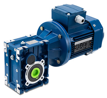
After purchasing a hyperbolic reducer motor, please carefully read the following instructions before use to ensure normal operation.
Preparation before installation
Rotation direction inspection: Before assembling the reducer with mechanical equipment, it is necessary to carefully check whether the rotation direction of the reducer output shaft is correct to ensure that it meets the equipment operation requirements.
Dimensional deviation inspection: Strictly inspect the deviation dimensions of various shaft diameters, hole diameters, keys, and keyways at the connection parts between the reducer, prime mover, and equipment. Ensure precise size matching to avoid adverse effects on the performance of the gearbox due to tight or loose assembly.
Installation environment inspection: Select a suitable installation location to ensure that the gearbox is securely installed without any looseness or vibration. At the same time, try to avoid exposing the reducer to direct sunlight and harsh natural environment, such as rainstorm, sand and dust, to prevent damage to the equipment.
Oil seal inspection (for long-term storage equipment): If the gearbox is stored for 4-6 months, it is necessary to check whether the oil seal is soaked in lubricating oil. Long term storage may cause the oil seal lip to stick to the shaft or even lose elasticity, and appropriate elasticity is a necessary condition for the normal operation of the oil seal. Therefore, it is recommended to inspect the oil seal and replace it if necessary.
Component cleaning inspection: Ensure that all rubber parts and vent surfaces are clean and free from impurities such as paint, to avoid affecting the normal operation and breathability of the equipment.
Installation process operation
Fixed installation: Use a suitable installation method to firmly install the reducer on the mechanical equipment. There are several common installation methods:
Flange installation: Connect the flange on the reducer to the corresponding flange on the equipment and fix it with bolts. This installation method is easy to operate, fast, convenient for adjustment and alignment, and suitable for most transmission scenarios.
Base installation: For reducers with heavy weight and strict vibration requirements, they can be installed on a dedicated base and then fixed to the equipment or foundation to ensure the stability and safety of the reducer operation.
Suspension installation: When space is limited or special angle transmission is required, the suspension installation method can be selected. During installation, it is essential to ensure that the suspension points are secure and reliable to prevent excessive vibration during operation.
Bracket installation: Use brackets to fix the reducer to the equipment, which is suitable for small reducers or situations with special structural requirements. The bracket installation can flexibly adjust the position and angle of the reducer to meet different transmission requirements.
Shaft connection operation: When connecting with the hollow or solid shaft of the reducer, a suitable amount of lubricating oil should be evenly applied to the mating part of the shaft to prevent the shaft from getting stuck or oxidized during operation, ensuring smooth operation of the connection part.
Precautions for motor connection (for motor direct type reducers): If various types of motor direct type reducers are used and the motor weight is relatively large, corresponding support devices should be set up to avoid excessive pressure on the output shaft of the reducer. At the same time, it is necessary to ensure a good ventilation environment near the motor fan to ensure the heat dissipation effect of the motor and prevent motor failure due to poor heat dissipation.
Check after installation
Oil level check: After installation, the oil level of the gearbox must be checked. The oil level can be observed through the oil level mirror hole. For some small models of reducers, it may be necessary to open the oil plug for inspection. Ensure that the oil level is within the normal range. If the oil level is too low, it should be replenished with lubricating oil that meets the requirements in a timely manner.
No load test run: When using a new gearbox, it is strictly prohibited to start at full load. A no-load test run should be conducted first to observe the operating status of the gearbox and check for any abnormal noise, vibration, or other conditions. After the no-load test run is normal, gradually increase the load to ensure that the gearbox enters a stable working state.
Steering inspection: After connecting the power supply, jog the motor and observe whether the rotation direction of the output shaft of the reducer is correct. For equipment such as hyperbolic mixers, the correct direction of rotation is usually counterclockwise when viewed from top to bottom. If the direction is opposite, switch the positions of the two power supply wires arbitrarily to correct the direction.
Installation orientation and parameter verification: The parameters given in this installation manual are basically prepared according to the B3 installation orientation, that is, the [related components] are not completely immersed in oil. If the actual installation orientation is different from B3 or the input speed changes, please refer to the corresponding parameter table to check and adjust the operating parameters of the equipment to ensure that the reducer operates under appropriate parameter conditions.
Key points of operation and maintenance
Load torque limit: The gearbox cannot withstand a large load torque exceeding twice the normal torque specified in the performance parameter table (when the coefficient fs=1). The high load torque here refers to the momentary and brief overload experienced during overload starting, braking, vibration, or other dynamic operating environments. It is necessary to strictly control the load to prevent damage to the gearbox due to overload.
Lubricating oil management
Oil change: For gearboxes, oil change must be performed after approximately 300 hours of operation (gear break in period). When changing the oil, the gearbox should be carefully rinsed with a suitable cleaning agent, and attention should be paid not to mix mineral oil and synthetic oil.
Regular testing: Oil quality and level should be checked every 3000 working hours, or at least every six months. At the same time, routine inspections should be conducted for dripping caused by inadequate sealing. If it is an IEC input gearbox, the elastic body needs to be tested and replaced if necessary.
Long term testing and replacement: According to different working conditions, conduct testing every three years, replace mineral oil, and replace bearing lubricating grease. In addition, according to actual working conditions, replace the oil seal on the output shaft in a timely manner to ensure good sealing performance and lubrication effect of the reducer.
Troubleshooting: When the product malfunctions, do not disassemble the components by yourself. It is necessary to contact the sales and service department of our company in a timely manner and provide detailed information such as specifications, manufacturing date, serial number, time of use, host name, host production unit, and fault type of the reducer, so that technical personnel can formulate reasonable maintenance measures.
Storage precautions
Storage environment: The gearbox should be stored in a covered, rain and snow resistant, and vibration free environment. If long-term storage is required, wooden blocks or other suitable materials should be placed between the equipment and the ground to prevent the equipment from getting damp or being affected by ground moisture.
Rust prevention treatment: For gearboxes that are not used temporarily after unpacking, rust prevention oil should be applied to their machined surfaces and promptly returned to the packaging box to prevent rusting of the machined surfaces. During regular inspections, for reducers stored for two years or longer, the focus should be on checking cleanliness, mechanical damage, and whether the rust proof layer is intact.
Product Identification Description
Model Marking: The reducer model marking includes key information such as reducer type, speed ratio, power, and installation method. During installation, maintenance, and equipment selection, it is necessary to accurately identify and record the model marking to ensure that the operation is consistent with the actual parameters of the equipment.
Surface coating color: The surface coating color of the reducer is generally provided in silver white. If there are special color requirements, please confirm with the manufacturer when ordering.
Related News