
Servo Motor: From Beginner to Proficient - Basic Principles and Troubleshooting Guide
Release Time:
2025-03-25
Servo motor is a closed-loop control system that achieves precise speed, torque, and position control through real-time feedback adjustment of output. Unlike the "open-loop blind running" of ordinary motors, it can dynamically correct errors based on the difference between instructions and feedback, with an accuracy of up to ± 0.001mm.
Servo Motor: From Beginner to Proficient - Basic Principles and Troubleshooting Guide
Starting from three aspects of common fault handling and maintenance techniques, let's thoroughly master the core points of servo motors together.
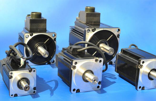
1、 Fundamentals of Servo Motor: Why is it smarter than ordinary motors?
1. Core Definition
Servo motor is a closed-loop control system that achieves precise speed, torque, and position control through real-time feedback adjustment of output. Unlike the "open-loop blind running" of ordinary motors, it can dynamically correct errors based on the difference between instructions and feedback, with an accuracy of up to ± 0.001mm.
2. Anatomy of core components
① Servo driver: the "brain" of the system, responsible for receiving instructions and inputting them
Send control signals.
② Servo motor: the "muscle" that executes actions, common types include permanent
Magnetic synchronous motor (mainstream), DC servo, etc.
③ Encoder: the "eye" of the system, implemented through photoelectric or magnetic sensing technology
Feedback the rotor position (with a resolution of up to 23 bits).
The Golden Rule of Selection
① Torque matching: needs to cover load inertia+acceleration torque, generally pre
Leave a 20% margin
② Speed requirement: Pay attention to the relationship between the rated speed of the motor and the reduction ratio
③ Accuracy level: Encoders with 17 bits or more are suitable for semiconductor equipment, etc
High precision scene
Top 10 High Frequency Fault Diagnosis Manual (with Solutions)
1. The motor howls and does not rotate
-Phenomenon: The driver displays an overload alarm (such as AL.50)
-Diagnostic steps:
Use a multimeter to measure the phase to phase resistance of UVW (normal value:
0.5-2Ω)
Measuring insulation resistance with a megohmmeter (should be>100M Ω)
Disconnect the coupling and test the no-load current (if abnormal, the shaft
Chengchi is stuck)
2. Accumulated positioning errors
-Classic case: A certain surface mount machine is offset by 0.1mm every time it returns to the origin
-Troubleshooting process:
Check the anti-interference of the encoder cable (grounding of the twisted pair shielding layer)
Verify electronic gear ratio calculation (numerator/denominator irreducible)
Wrong classification)
Replace the coupling to eliminate backlash (switch to a diaphragm coupling)
3. Abnormal vibration during motor operation
-Spectrum analysis:
① 600Hz peak → driver carrier frequency interference (adjust PWM)
Frequency)
② 50Hz frequency doubling → mechanical resonance (installation of shock absorbers or modification of notch)
Filter parameters
4. Zero point loss of encoder
-Emergency response:
① Execute the reset process of the value encoder (refer to the manufacturer's manual)
② Replace the battery (applicable to memory encoders with batteries)
③ Redo the origin calibration (using a micrometer to assist in positioning)
Related News