
Internal structure of common right angle shaft reducers
Release Time:
2025-03-21
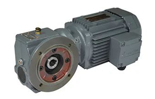
This type of reducer is generally more common in the design and selection of non-standard automation equipment. Examples of models include the S series and K series of the four major series of reducers.
Internal structure of common right angle shaft reducers
This type of reducer is generally more common in the design and selection of non-standard automation equipment. Examples of models include the S series and K series of the four major series of reducers.
The mortar mixing box of the shield tunneling machine can also use this type of reducer, paying attention to the model and lubrication method used. Usually used diagonally, with lubrication accessories added externally to ensure lubrication.
The reducer is mainly composed of transmission components (gears or worms), shafts, bearings, housings, and their accessories. Its basic structure consists of three main parts: (1) gear, shaft, and bearing combination; (2) Box body; (3) Gearbox accessories.
The principle of mechanical gearbox: You can briefly understand the following.
The mechanical gearbox mainly applies the principle of gear transmission to reduce speed. Simply put, there are multiple sets of gear pairs with different transmission ratios in the gearbox, and the shifting behavior of the car during driving is achieved by manipulating the mechanism to make the different gear pairs in the gearbox work. At low speeds, let the gear pair with a larger transmission ratio work; At high speeds, let the gear pair with a smaller transmission ratio work.
There are two types of right angle reducers:
1. Worm gear reducer
worm and worm gear
Worm: usually cylindrical in shape, with spiral teeth (single or multiple heads) machined on the surface, mostly made of quenched steel, with high wear resistance.
Worm gear: made of bronze or cast iron, with teeth that match the worm screw, transmitting power through sliding friction, with low efficiency (usually 50% -90%), but with self-locking characteristics (when the lead angle is less than the friction angle).
bearing system
The two ends of the worm are equipped with angular contact ball bearings or tapered roller bearings to withstand axial thrust.
The worm gear shaft uses self-aligning roller bearings to accommodate possible installation errors.
Lubrication and Sealing
Oil bath lubrication is common, and lubricating oil needs to have pressure and anti-wear properties (such as EP gear oil).
Seals often use skeleton oil seals or labyrinth seals to prevent oil leakage and contamination.
casing
The cast iron shell is designed with heat dissipation ribs, and some high-speed models integrate fans for forced cooling.
2. Spiral bevel gear reducer
Gear pair
Spiral bevel gear: The tooth surface is curved and gradually contacts during meshing, reducing impact noise and having a higher load-bearing capacity than spur bevel gears.
The gears are treated with carburizing and quenching, and the accuracy level is usually above AGMA level 10.
bearing arrangement
The input/output shaft adopts a tapered roller bearing group, and pre tension adjustment is used to control axial clearance.
High precision models may use cross roller bearings to ensure rigidity.
lubrication system
Splash lubrication is the main method, and large reducers are equipped with oil pumps for forced circulation and oil coolers for temperature control.
shell structure
The split design facilitates gear adjustment, with high precision machining of the joint surface, and avoids oil leakage.
Related News