
Installation and daily maintenance of gear reduction motor
Release Time:
2024-09-14
Gear reduction motors generally achieve the purpose of deceleration by meshing the input shaft of an electric motor, internal combustion engine, or other high-speed power through gears with fewer teeth on the output shaft of the gear reduction motor.
Working principle of gear reduction motor
Gear reduction motors generally achieve the purpose of deceleration by meshing the input shaft of an electric motor, internal combustion engine, or other high-speed power through gears with fewer teeth on the output shaft of the gear reduction motor.
2. Structural Decomposition Diagram
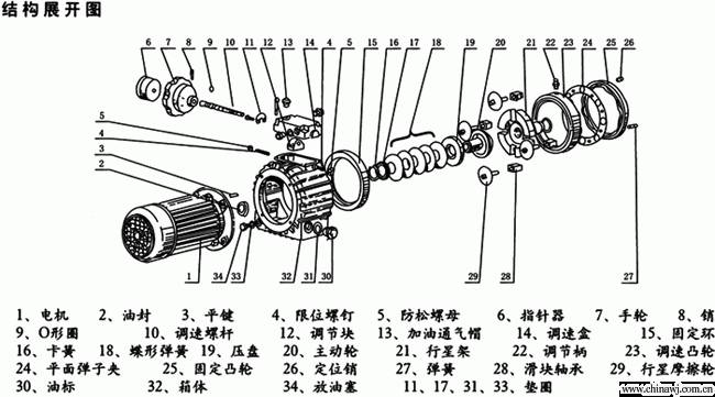
Characteristics of 3 gear reduction motors
1. The gear reduction motor is manufactured according to the national professional standard ZBJ19004 production technology requirements, with high technological content;
2. Space saving, reliable and durable, with high overload capacity and a power output of over 95KW;
3. Low energy consumption, superior performance, and gearbox efficiency of over 95%;
4. Low vibration, low noise, high energy saving, using high-quality steel materials, steel cast iron box body, and high-frequency heat treatment on the gear surface;
5. After precision machining to ensure positioning accuracy, the gear reduction motor of the gear transmission assembly is equipped with various types of motors, forming an integrated mechanical and electrical system, fully ensuring the quality characteristics of product use;
6. The product adopts a series and modular design concept, with wide adaptability. This series of products has an extremely large number of motor combination installations, installation positions, and structural schemes, and can choose any speed and various structural forms according to actual needs.
Precautions to be taken before installing a gear reduction motor
1. Precautions before installing the deceleration motor
Before installation, check the nameplate requirements on the deceleration motor to see if the power supply matches.
Check if the deceleration motor and reducer are intact.
The requirements for the working environment should be in a place free of oil, acid, alkali, harmful gases, steam, radioactive substances, etc.
2. When installing transmission components on the output shaft, it is not allowed to strike them with a hammer. Usually, assembly fixtures and internal threads on the shaft end are used to press the transmission components in with bolts, otherwise it may cause damage to the internal parts of the reducer. It is best not to use rigid fixed couplings, as improper installation of such couplings can cause unnecessary external loads, leading to early damage to bearings and even fracture of the output shaft in severe cases.
3. The worm gear reduction motor cannot apply a large load of reverse transmission to the reducer (self-locking).
4. Thoroughly remove preservatives, dirt, and other contaminants from the shaft extension, flange, and key surfaces with solvents. When removing, be careful not to let the solvent soak into the oil seal, otherwise the solvent may damage the oil seal.
5. The installation foundation of the deceleration motor should be a strong, rigid, vibration reducing, and torsion resistant base, platform, or other supporting structure, and the foundation must be dry and free of grease.
6. Products with both bottom legs and installation flanges should be strictly prevented from competing with each other during installation.
7. The minimum performance level of the basic spiral is 8.8.
8. It is recommended to use elastic couplings for the couplings between the working machines of the deceleration motor.
9. The force points of radial loads on couplings, brakes, clutches, and gears installed on the input and output shafts should be as close to the shaft shoulder as possible.
10. When connecting the hollow output shaft with a key to the working machine shaft, anti rust oil should be applied. When installing, it should be easily pushed in or pulled in with a screw. The hollow output shaft with a tension plate should not have any oil or grease on the end with the tension plate, and the other end can be coated with anti rust oil.
11. The input and output shafts of the deceleration motor, as well as the shafts of the prime mover and working machine, should be strictly aligned and coaxial. This requirement can reduce vibration and noise, extend the life of the bearings, and ensure the normal operation of the deceleration motor.
12. To prevent accidents, rotating parts should be equipped with protective covers and covers according to safety requirements.
13. Ensure that the ventilation caps of each deceleration motor are installed correctly and ensure smooth ventilation. Install the device according to regulations to ensure that personnel can easily access the oil gauge, vent plug, and drain plug. After installation, the accuracy of the installation position and the reliability of the tightening of each fastener should be comprehensively checked in order. After installation, it should be able to rotate flexibly. The reducer adopts oil pool splash lubrication. Before operation, the user needs to remove the screw plug of the vent hole and replace it with the vent plug. According to different installation positions, open the oil level plug screw to check the height of the oil level line. Add oil from the oil level plug until the lubricating oil overflows from the oil level plug screw hole. After confirming the correctness of the oil level plug, perform a no-load test run for no less than 2 hours. The operation should be smooth, without impact, vibration, noise, or oil leakage. Any abnormalities should be promptly eliminated.
14. When installing torque, it should be done in a mutually free state.
15. The installation lock must be firm and reliable, and must not cause displacement during operation.
16. Be sure to install grounding devices to prevent electric shock accidents.
Daily maintenance points for 5 gear reduction motors
1. The deceleration motor should be regularly cleaned of oil stains, dust, and kept clean to facilitate heat dissipation.
2. Damaged oil seals should be replaced promptly.
3. The oil level should be checked regularly, and if the oil level is insufficient, it should be replenished immediately.
4. Lubricating oil should be replaced regularly: When a new machine is first used, the lubricating oil should be replaced after running for 7 to 15 days. In the future, it can be replaced every 3 to 6 months according to the machine's usage. It should be noted that the power should be cut off when changing the oil to ensure safety. When checking the oil, if obvious turbidity is found in the lubricating oil, it is recommended to replace it as soon as possible.
5. Attention should be paid to the fact that lubricating oils of different qualities cannot be mixed for use.
6. The use and maintenance of electric motors should be carried out in accordance with the motor's user manual.
7. When the oil temperature rises above 80 ℃ or the oil pool temperature exceeds 100 ℃ and abnormal noise is generated during work, the use should be stopped, the cause should be checked, the fault must be eliminated, and the lubricating oil must be replaced before continuing to operate.
8. Users should have reasonable usage and maintenance rules and regulations, and carefully record the operation of the reduction motor and any problems found during inspection. The above regulations should be strictly implemented.
Related News