
The control method of a clear and concise stepper motor
Release Time:
2025-03-03
Stepper motor, also known as stepper, utilizes electromagnetic principles to convert electrical energy into mechanical energy. People began using this type of motor as early as the 1920s. With the increasing popularity of embedded systems such as printers, disk drives, toys, wipers, vibrating pagers, robotic arms, and video recorders, the use of stepper motors has also begun to surge.
The control method of a clear and concise stepper motor
Stepper motor, also known as stepper, utilizes electromagnetic principles to convert electrical energy into mechanical energy. People began using this type of motor as early as the 1920s. With the increasing popularity of embedded systems such as printers, disk drives, toys, wipers, vibrating pagers, robotic arms, and video recorders, the use of stepper motors has also begun to surge.
Whether in industry, military, medical, automotive, or entertainment, stepper motors are always useful for moving an object from one location to another. There are many shapes and sizes of stepper motors, but regardless of their shape and size, they can be classified into two categories: variable reluctance stepper motors and permanent magnet stepper motors. This article focuses on the simpler and more commonly used permanent magnet stepper motor.
Construction of stepper motor
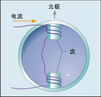
A stepper motor is driven by a set of coils wound around the stator slots, which are fixed components of the motor. Normally, a coiled metal wire is called a solenoid, while in a motor, the metal wire wound around the teeth is called a winding, coil, or phase. If the current flow in the coil is as shown in Figure 1, and we look down at the top of the tooth slot from the top of the motor, then the current flows counterclockwise around the two tooth slots. According to Ampere's Law and the right-hand rule, such a current will generate a northward magnetic field.
Now suppose we construct a motor with two windings wound around the stator, which contains a permanent magnet that can rotate freely around the center. This rotatable part is called the rotor. Figure 2 shows a simple motor called a dual phase dual motor, as it has two windings on its stator and two magnets on its rotor.
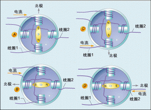
If we supply current to winding 1 in the direction shown in Figure 2a and no current flows through winding 2, then the south of the motor rotor will naturally point towards the north of the stator magnetic field as shown in the figure.
Assuming we cut off the current in winding 1 and supply current to winding 2 in the direction shown in Figure 2b, the magnetic field of the stator will point to the left, and the rotor will also rotate in the same direction as the stator magnetic field.
Next, we cut off the current of winding 2 and supply current to winding 1 in the direction shown in Figure 2c. Note that the current flow in winding 1 is opposite to the direction shown in Figure 2a. So the magnetic field of the stator will point downwards, causing the rotor to rotate, and its south will also point downwards.
Then we cut off the current in winding 1 and deliver current to winding 2 in the direction shown in Figure 2d. As a result, the stator magnetic field will point to the right again, causing the rotor to rotate and its south direction to also point to the right.
Afterwards, we cut off the current in winding 2 again and supply the current shown in Figure 2a to winding 1, so that the rotor will return to its original position.
At this point, we have completed one cycle of electrical excitation on the motor winding, and the motor rotor has rotated a full circle. That is to say, the electrical frequency of the motor is equal to the mechanical frequency at which it rotates.
Related News