
A Brief Discussion on the Mechanical Characteristic Curve of Three phase Asynchronous Motor
Release Time:
2024-09-11
The function of a motor is to provide a certain torque to the working machinery and enable it to operate at a certain speed. Torque T and speed n are two basic requirements for motors in production machinery. The mechanical characteristics of a motor refer to the relationship between the torque T generated on the motor shaft and the corresponding operating speed p under certain conditions of stator voltage, frequency, and winding parameters. As shown in the above figure, this curve indicates the main performance indicators of the motor and is also the basis for selecting the motor. Several key 'points'
What are the inherent mechanical characteristics of a motor?
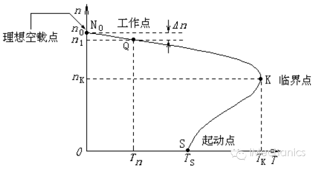
The function of a motor is to provide a certain torque to the working machinery and enable it to operate at a certain speed. Torque T and speed n are two basic requirements for motors in production machinery. The mechanical characteristics of a motor refer to the relationship between the torque T generated on the motor shaft and the corresponding operating speed p under certain conditions of stator voltage, frequency, and winding parameters. As shown in the above figure, this curve indicates the main performance indicators of the motor and is also the basis for selecting the motor. Several key 'points'
1. The starting point S is at this point, with a speed of n=0 and a slip rate of s=1. The corresponding torque here is called the starting torque Ts, and the current is the starting current Is.
At the critical point K, the motor torque reaches its maximum. It is also the boundary point between the stable operation zone and the unstable operation zone of the motor.
3. The working point Q is at point c, and the motor is in its rated operating state. At this time, the corresponding torque is the rated torque Tn.
4. Ideal no-load point N0, also known as the "synchronous speed point", has a slip rate of s=0. Due to the lack of relative motion between the rotor and the magnetic field, the torque T=0, which belongs to an ideal state.
Several key 'indicators'
1. Rated torque Tn refers to the output torque on the motor shaft when the motor operates at rated speed and outputs rated power at rated voltage. This is also the parameter we usually calculate the most frequently. The formula is: Tn=9550P/n.
2. The starting torque Ts is an important indicator for measuring the starting performance of a motor. A high starting torque results in a high motor acceleration and a short starting time. It reflects the ability of the motor to start with heavy load. The motor can only start when the starting torque is greater than the load torque on the motor shaft.
3. The maximum torque Tk is the ability of the motor to drive the maximum load. During the process of starting and normal operation of the motor, the electromagnetic torque is constantly changing, as shown in the previous figure. The maximum value is called the maximum torque.
4. The ratio of the difference between the rotating magnetic field speed n0 and the rotor speed n1 to the synchronous speed n0 is called the slip rate, and the slip rate corresponding to the critical point is called the critical slip rate Sk.
The ratio of the maximum torque Tk to the rated torque Tn is called the overload factor, which reflects the overload capacity of the motor. The overload multiple of a general asynchronous motor is λ m=1.5-2.5.
6. The ratio of starting torque to rated torque is called starting torque multiple or locked rotor torque multiple, which characterizes the starting ability of the motor. Generally, the starting torque multiple of asynchronous motors is ks=1.6-2.2.
Three expressions for electromagnetic torque of asynchronous motors
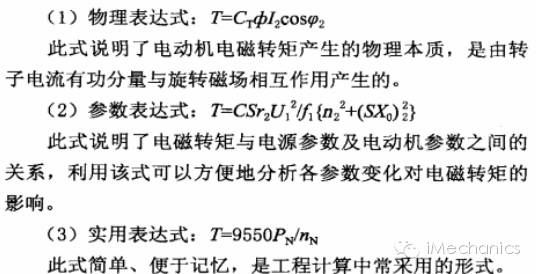
The mechanical characteristics of a motor can be expressed not only by the curves mentioned above, but also by functions. When expressed as a function, there are three types of expressions:
In the above expression, C is the torque coefficient, Φ is the main magnetic flux, I2 is the converted value of rotor current, U1 is each voltage, f1 is the frequency, r2 is the rotor circuit resistance, n2 speed, S slip rate, and x reactance.
From the parameter expressions above, it can be seen that changing the stator voltage U1, stator frequency f1, pole pairs p, stator circuit resistance r1 and reactance x1, rotor circuit resistance r2 ˊ and reactance x2 ˊ can all result in different artificial mechanical characteristics. The mechanical characteristics obtained by artificially changing the electrical parameters of the motor are called "artificial mechanical characteristics", which are different from the inherent mechanical characteristics of the motor mentioned earlier. Several 'artificial mechanical characteristics' of motors
Characteristics: 1) Voltage drop, increasing slope of linear segment, softening of characteristics, significant decrease in starting torque multiple and overload capacity. 2) A decrease in voltage and electromagnetic torque will lead to a decrease in motor speed, an increase in rotor current and stator current, resulting in motor overload. When the voltage drops too much and the maximum electromagnetic torque is less than the load torque, the motor may even stop running.
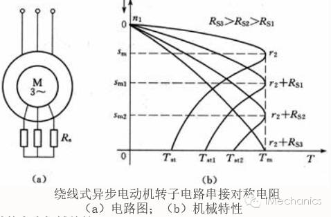
Features: When increasing the resistance of the rotor circuit, the synchronous speed and critical torque remain unchanged; The critical slip rate increases. The slope of the linear segment increases, and the characteristics become softer. Appropriately increasing the resistance of the rotor circuit can increase the starting torque of the motor.
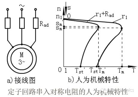
Characteristic: When increasing the stator circuit resistance, the synchronous speed remains unchanged, but the critical torque, critical slip rate, and starting torque all decrease.
Related News