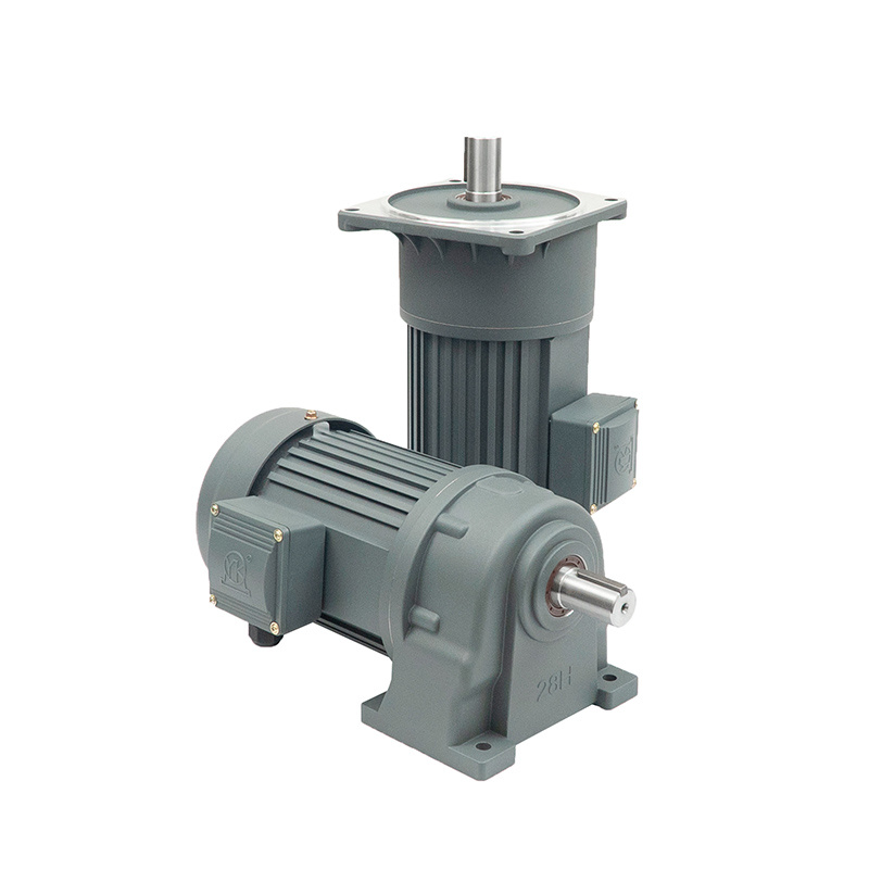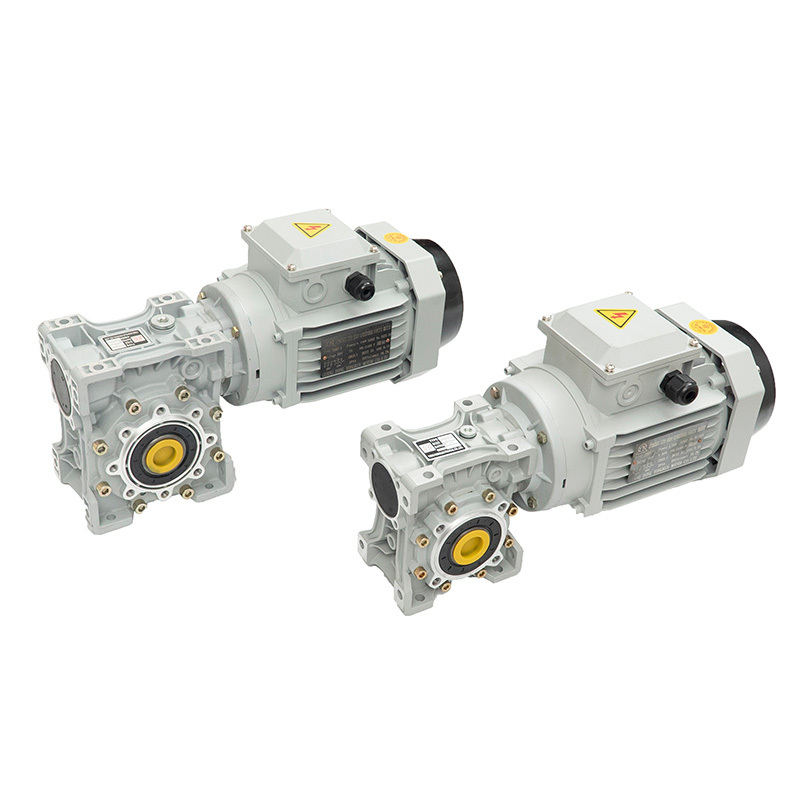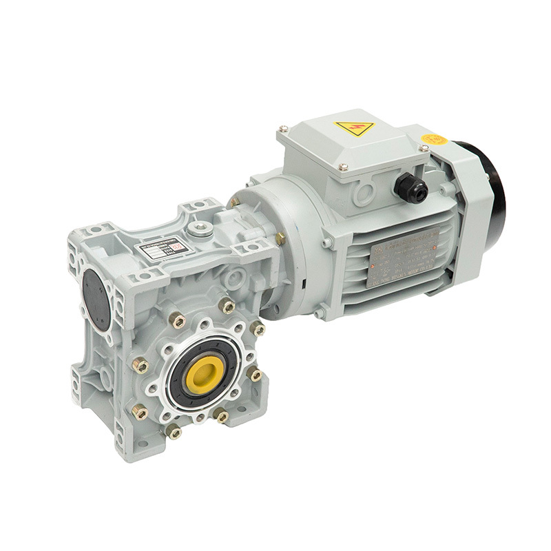
Gear Motor
1. When the reducer shaft is used with the mechanical connection of sprocket, conveyor belt and gear, the output shaft allowable O.H.L should be considered. 2. The list of allowable O.H.L value load position in the (solid shaft: the middle of the output shaft; hollow shaft: at 20mm from the end of the shaft) 3.15 than the load inertia can not be greater than 2 times the allowable shaft rotation
Keywords
Motor / Reducer
Category
Product Brochure
Product Details
| Model | ZS | 1 |
| Shaft diameter | 35 | 2 |
| Shaft head type | H | 3 |
| Shaft direction | L | 4 |
| Motor power | 400W | 5 |
| Reduction ratio | 15 | 6 |
| Voltage | S | 7 |
| Brakes | B | 8 |
| Junction box location | G1 | 9 |
| Outlet direction | T | 10 |
| 1.Model | ZF right angle gear motor, flange mounted |
| 2.Shaft diameter | Hollow shaft type is inner diameter, solid shaft type is outer diameter |
| 3.Shaft head type | H:Hollow shaft S:Solid shaft |
| 4.Outgoing shaft direction (from the wind cover) | L:Left exit shaft (standard model) R:Right exit axis T:Left and right exit shaft |
| 5.Motor power | 0.1KW 0.2KW 0.4KW 0.75KW 1.1KW 1.5KW 2.2KW |
| 6.Reduction ratio | 5-1000 |
| 7.Voltage | S:Three phase C:Single Phase |
| 8.Brakes | B:With brake Blank: Without brakes |
| 9.Junction box location (from the airfoil cover) | G1:Standard Location Junction box position G2, G3, G4 selectable |
| 10.Outlet port direction (from the airfoil cover, the reducer head is in front) | F:Front (from deceleration head) L: Left T: Top B:Rear (from wind shield) (standard type) R: Right D: Down |
Previous
Next
Previous
Next
Related Brochure Download
蜗杆图册

瑞思科伺服电机
瑞思科齿轮
精密行星
2021永坤马达第二版
Related Products